Hello all, the following how to is a project of mine i have been thinking about doing for a year or so now, and just spent the last couple months planning it out. Before i get started i want to let everyone know that i make my how to threads very detailed, and plan to continue to add tech to this forum and should anyone have any questions on anything electrical, send me a PM and ill do my best to answer. Also i wanted to prove to anybody questioning any project with a 'can it be done' thought, that yes with enough planning, trial and error, and effort, anything can be done.
So a little background on this project, i have been wanting to do this updated look for a few reasons:
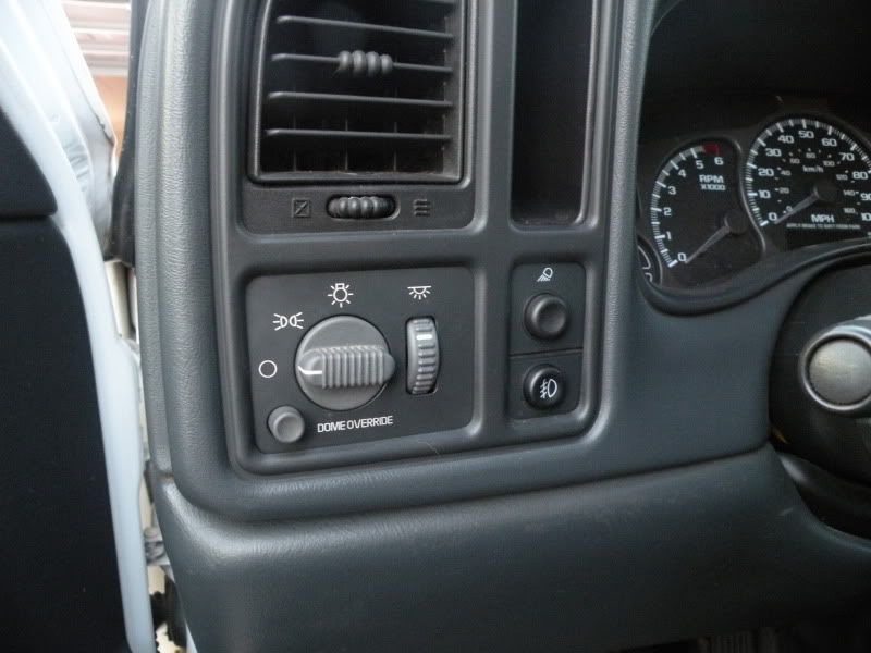
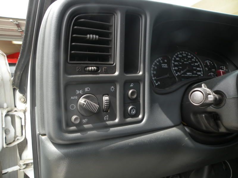
1) Every 99-02 owner knows that in order to turn your headlamps off in AUTO mode you have to press the dome override button 4 times. With the 03-07, you can turn the switch backwards to override the headlamps. This is programmed into the BCM.
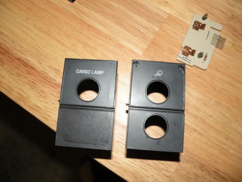
2) The 99-02's have a lighter gray colored switch panel to them, whereas the 03-07 have a darker graphite shade, as well as the knobs on both switches relate in color to the corresponding controls as well. I like the updated look.
3) I like challenges.
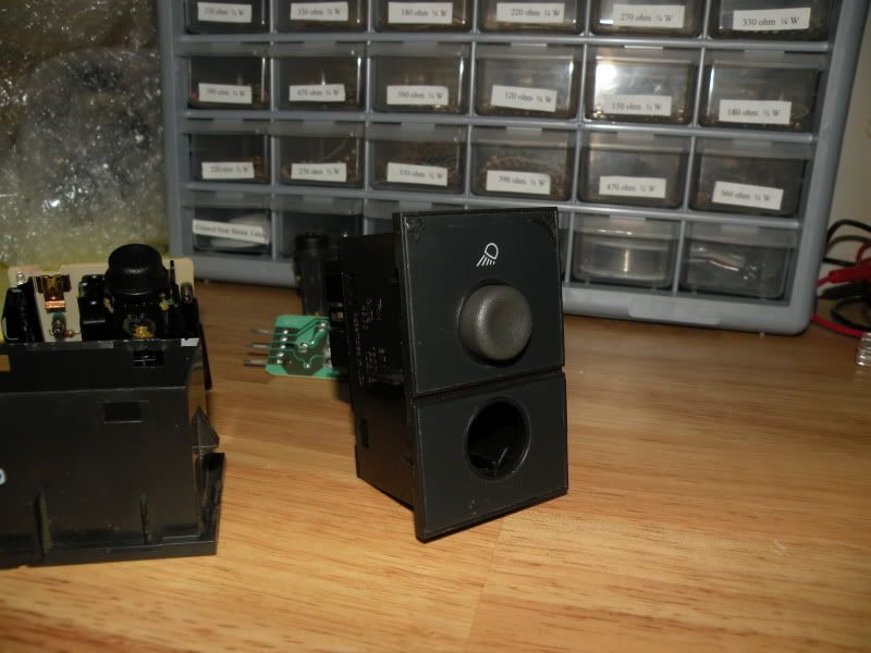
I have also adapted the updated cargo/foglight switch which was super simple to do, and its one of those little things that cleans up the appearance as well. That can be found in another thread:
http://customgm.com/f14/how-replace-99-02-foglight-switch-03-07-a-1004.html
Now onto the technical part of this whole thing. The 99-02 trucks run off of a positive trigger. Meaning almost everything in the vehicle has ground applied the whole time, until you give it 12v power. 03-07 trucks have negative trigger, which is opposite...almost everything is powered, but needs to be grounded (have a negative trigger given) to them to complete the circuit. That right there is a big problem in the way both switches work. To make the updated switch work in a 99-02 platform you need to modify a few parts internally. This may be a little overwhelming to some people but with decent soldering skills you can pull it off flawlessly.
Schematic's you will need:
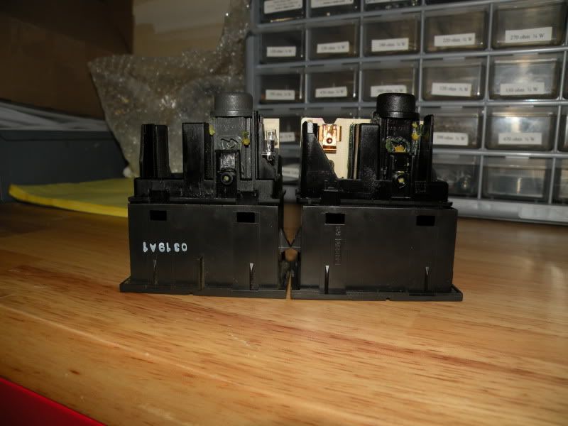
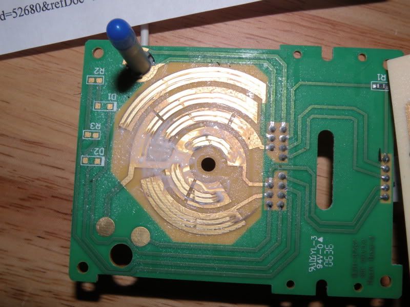
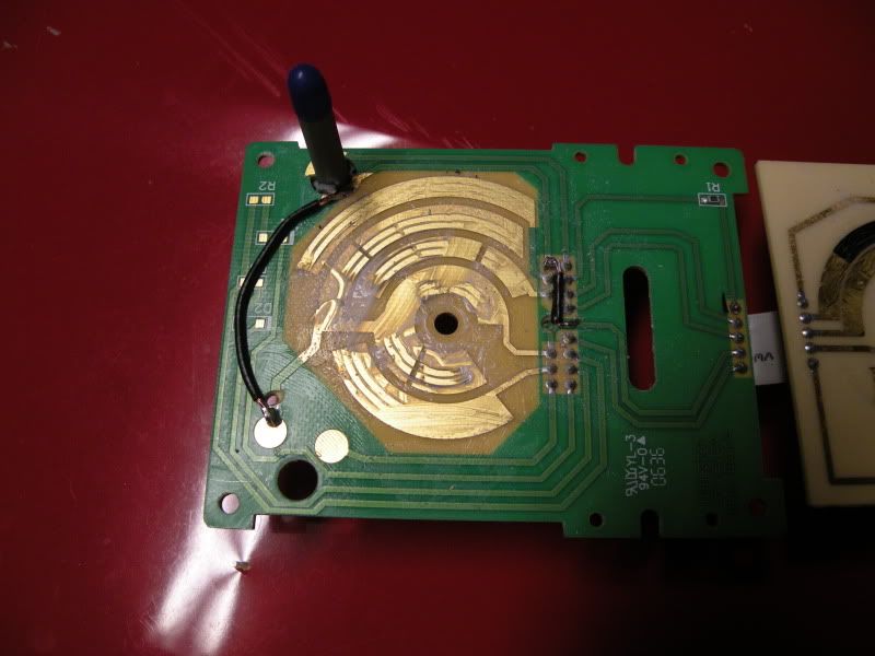
First things first, this is how the inside of a circuit panel looks like for the 03-07 headlamp switch.
Ground is the main circuit tracer in the middle, as you can see with every revolution or contact within the panel, ground will be applied to another tracer to trigger the attached wire.
We will now need to modify this switch to work as a positive trigger. Note: this switch is set up as a negative trigger so everything that NEEDS a ground trigger to work needs to be removed from the circuit path.
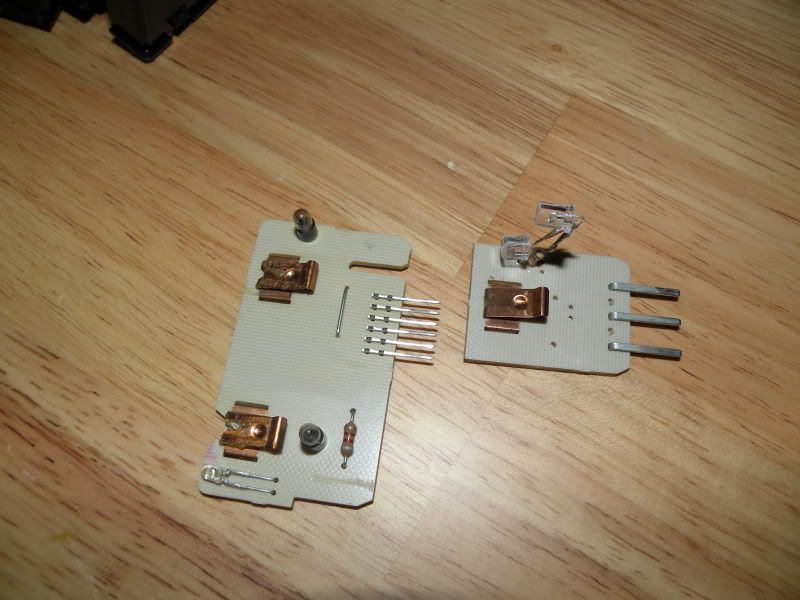
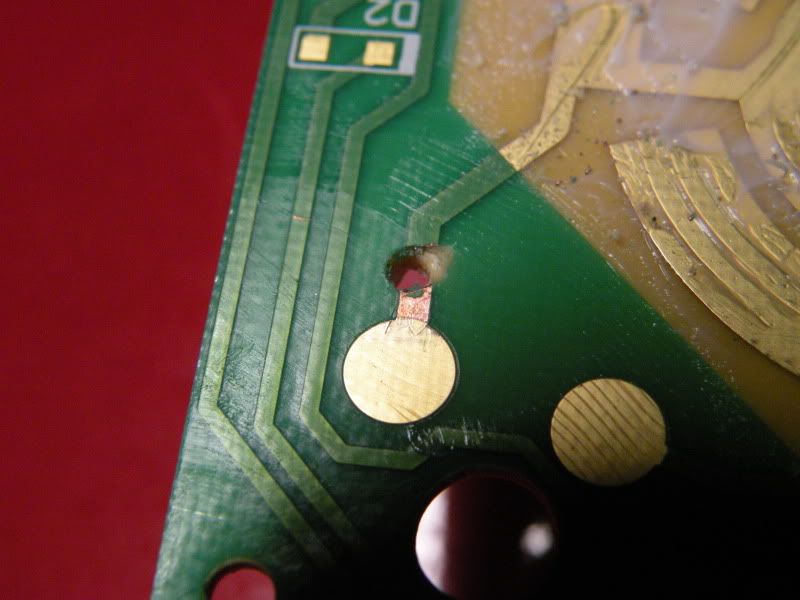
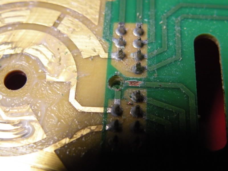
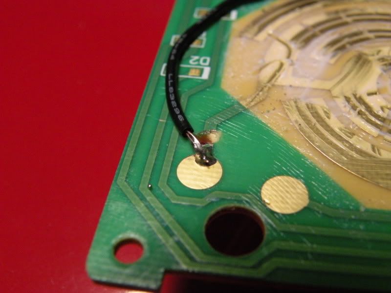
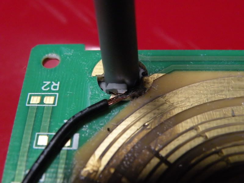
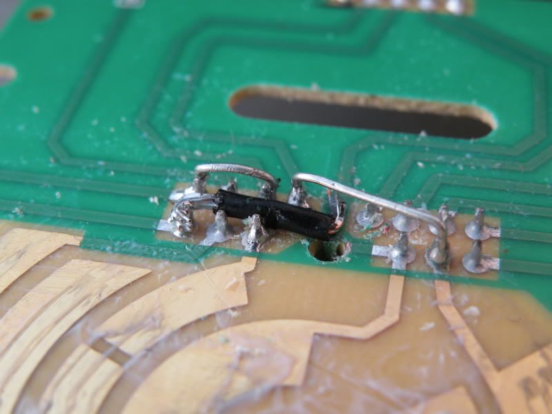
You need to drill 2 holes with an 1/8" bit or a bit big enough to sever the tracer from making contact. Ive provided a couple of photos to show where to drill. This will keep these 2 circuits from receiving +12v. One is for the dome/courtesy override and the other is for the dome light.
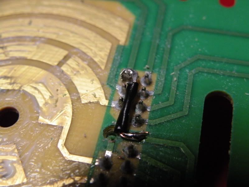
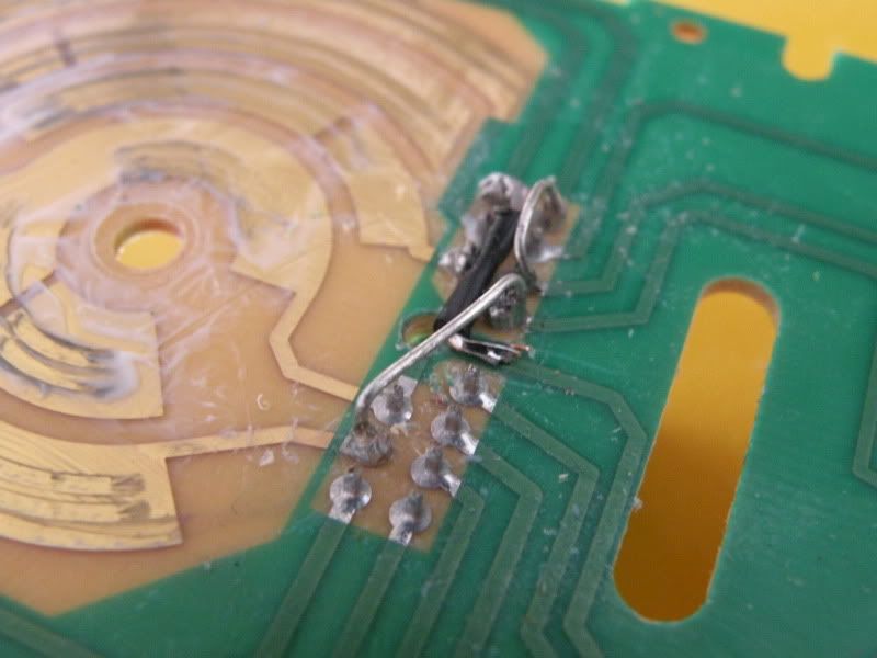
As you can see in the above photo's i have scratched the copper tracer up a little so i can solder to it. We will be using a piece of wire (or whatever you can think of) to connect both of these tracers to the ground circuit. We will be using the ground tracer going to the light inside the switch itself as our main ground. So we need to attach the dome light tracer to the ground pin (#6) with a tiny piece of wire as shown:
And attach a longer piece of wire to the dome override circle and to the light tracer AT the light:
And it will look like this:
In case you're wondering, the bottom 3 right hand side pins will not be used. They go to the LED's that would indicate which mode you're in by turning the switch knob. Some upgraded vehicles such as fully loaded trucks, as well as escalades had the LED indicators.
Now we need to attach the parking lamp pin (#2) to the dimmer input pin (#11) with a jumper wire. As well as attach the internal light pin (#14) to the dimmer return pin (#12). This will allow the dimmer to receive power once the parking lamps and illumination lamps get switched on. And by connecting the internal lamp to the dimmer return pin, this gives the internal lamp its trigger to power on as well.
Now we are DONE internally. Everything will act as it should when using the switch as normal.
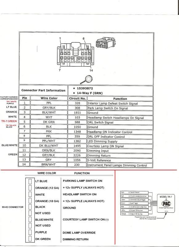
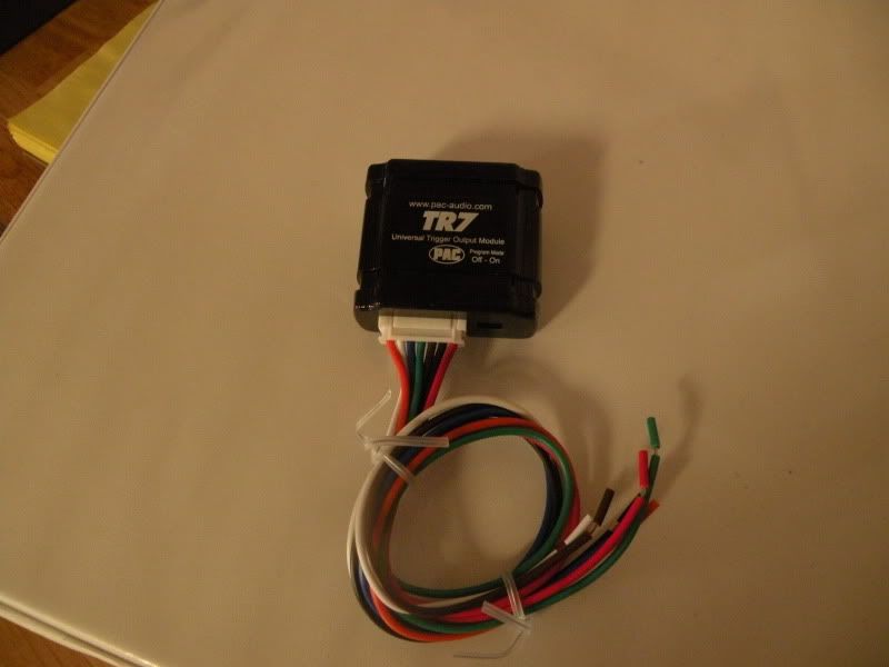
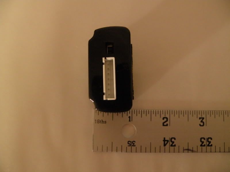
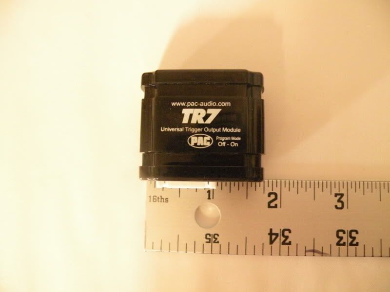
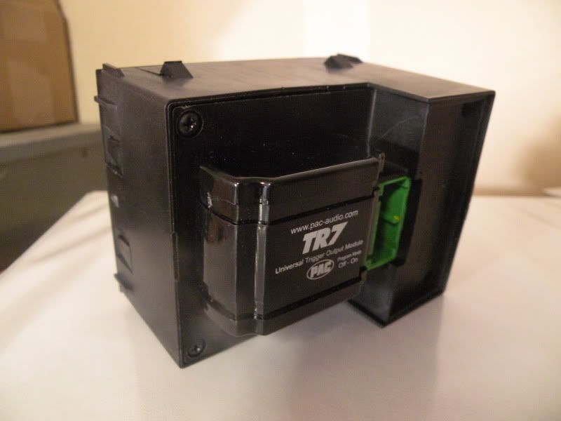
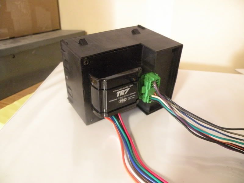
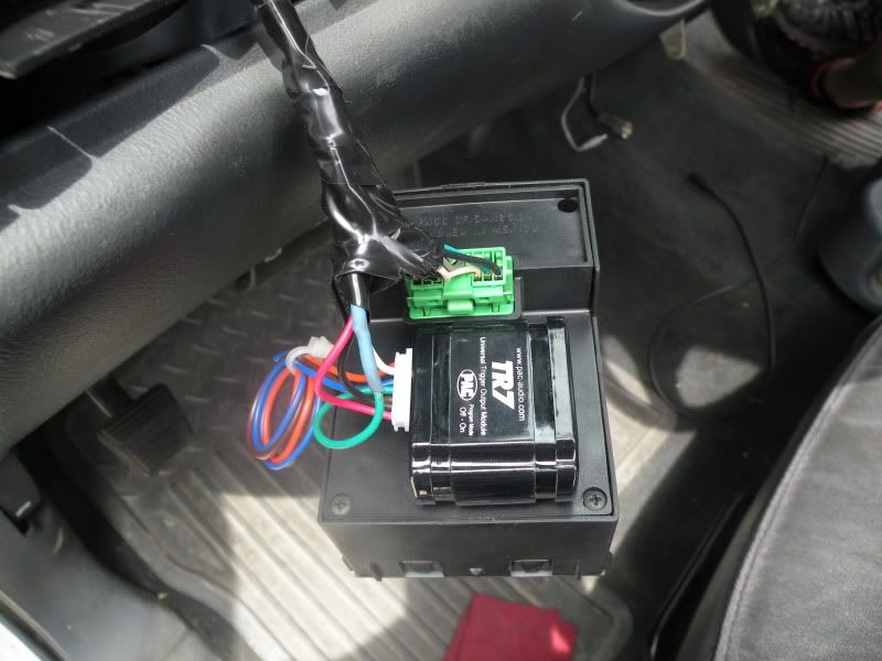
Now to move to the outside wiring. A brief explanation on the factory wiring. I have included a diagram at the top to show the pin location and wiring color for the harness you will need to buy for your updated switch. I have also included on that page a badass msPaint schematic i did of the 99-02 connector with wire funtions/color, and a quick schematic of the PAC TR-7 module you will need to buy ($20 on ebay).
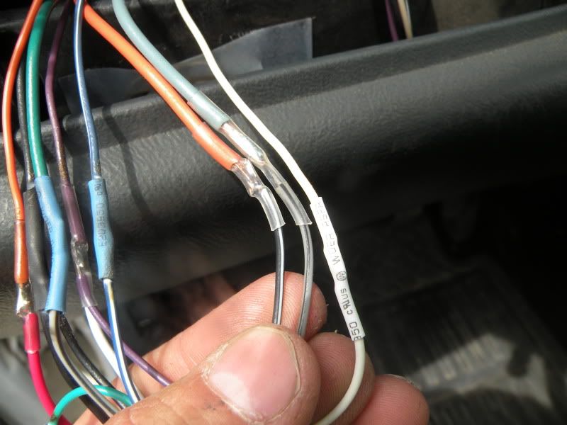
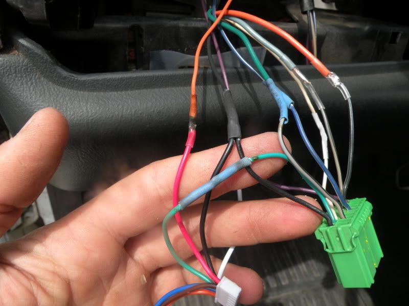
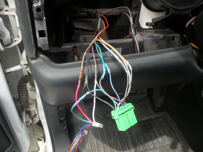
In the schematic above on the left hand side you will see the factory wire color that needs to be crimped/soldered/connected however you choose, to the 14-way connector. Ill tell you this right now, if you have access to the connector crimp on pins, you can make this look like almost a factory install by crimping them onto the factory wires and plugging them into the new connector. I chose the solder/heatshrink method.
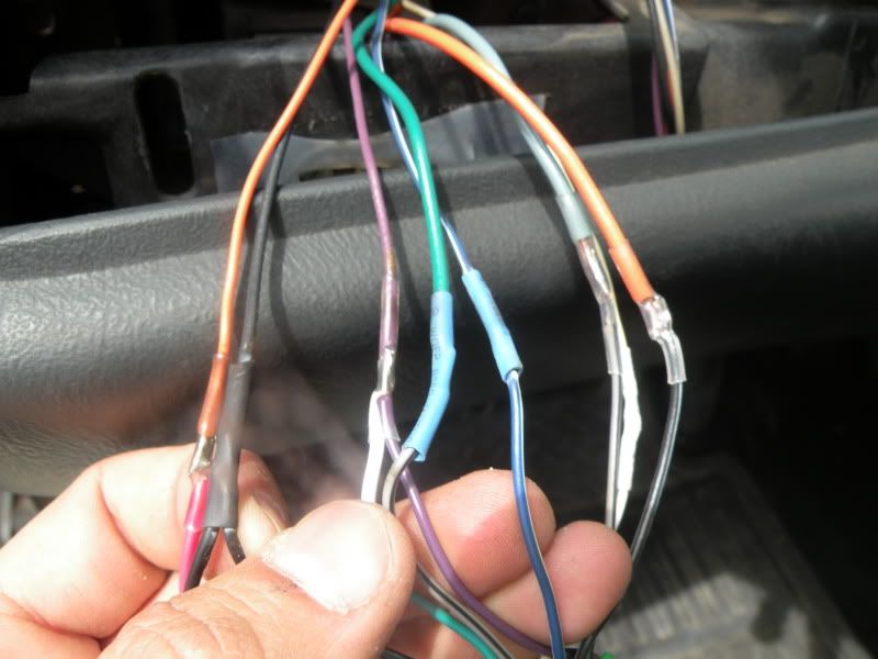
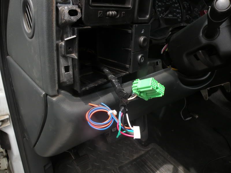
Here are a few pictures showing exactly where each one will go....it would be pointless to explain why/where when the answer is in the schematic. If you have any questions i would be happy to answer them to make it a little more clear and understanding.
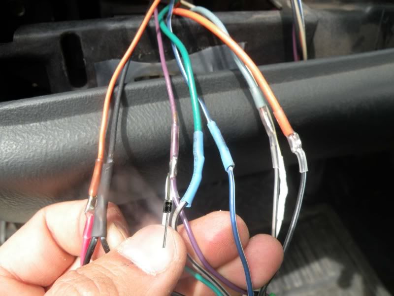
Edit: This picture ^ shows the white wire with a Diode placed over it. I forgot about this completely but have gone back and soldered a 12v diode in place. I think the part number is a 1N4004. Anyways you need this diode on the white wire for the TR7 module with the stripe facing away from it. This will keep the normal pulses from your dome override button from backfeeding into the unit causing your dome light to flash twice. You can get a 2-pack of these diodes for a buck.
1N4004 Micro 1-Amp Rectifier Diode - RadioShack.com